|
The joule thief (aka blocking oscillator) is an electronic circuit that allows you to make use of batteries normally considered dead. A battery is often considered "dead" when it can't power a particular device. But what's really happening is that the battery voltage is no longer high enough for the device when it's used directly. The joule thief circuit massages the voltage and current coming from the battery so that the voltage is high enough, for periods of time, for the device to work continuously.
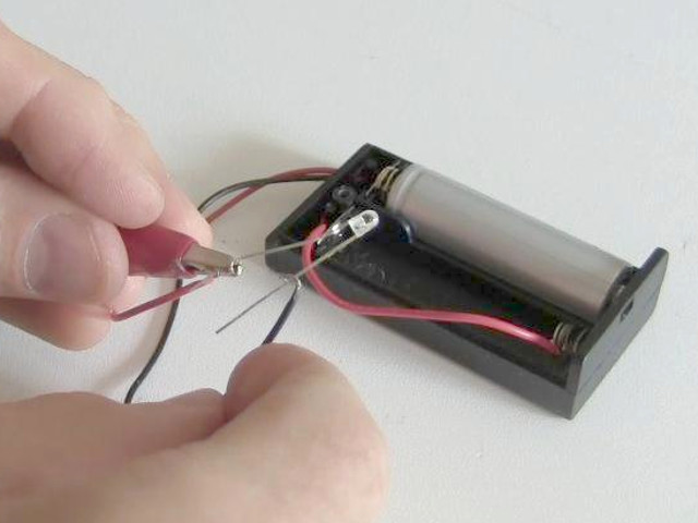
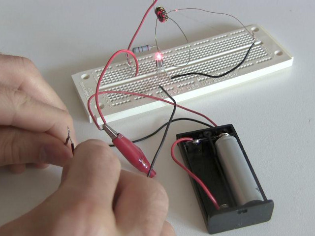
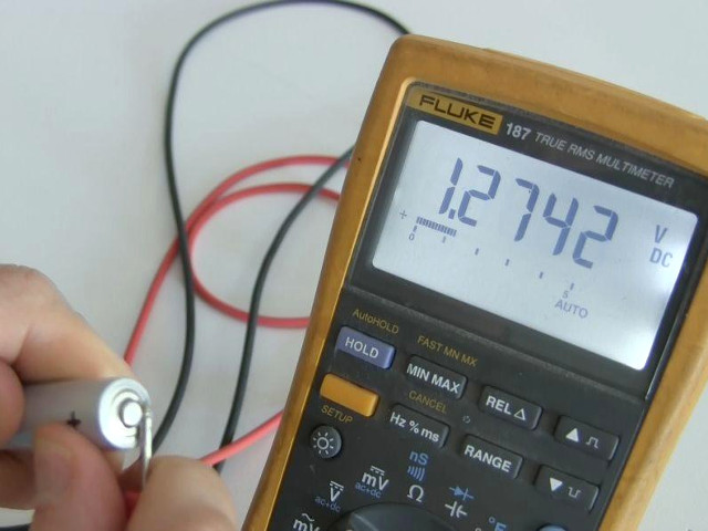
The LED in the above photo requires 1.85 volts but as the photo below shows, the battery voltage is only 1.27 volts. When run through the joule thief circuit, the voltage is as high as 24 volts, as shown in the oscilloscope output n the photo on the right. Notice that the LED is not always getting power, but it's often enough to keep it lit.
What the joule thief can runIt's simple to get it to run an LED for a long period of time, even starting with a battery with less that 1 volt.
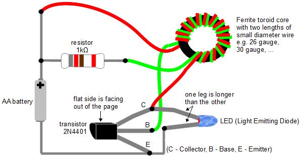
How to make a joule thiefHere is the joule thief circuit used in the above photos.
Transistor - The legs of the transistor can be determined by noticing that there's a flat side to the transistor case. See the diagram above. A large number of transistors have been reported to work: 2N4401, NET123AP, BC547B, 2SC2500, BC337, PN2222, to name just a few. LED - One leg of the LED is longer than the other leg. Use this to determine which one goes where. See the diagram above. Resistor - The diagram says use a 1 kilo ohm resistor but I've used an 820 ohm one just fine. I've also seen a 2 kilo ohm one in use. Use whatever works for you. You can also use a potentiometer (a variable resistor) so that you can easily adjust it to select the resistance that gives the best light. Toroid ferrite core - Some people have gotten these by opening up compact fluorescent lightbulbs (CFLs). I took mine out of some device whose original function I don't know. To get it working, my first one had just 13 turns for each wire and I used a 30 gauge wire and a 26 gauge wire. The wire must be insulated. A variety of number of turns will work. This is something you can play with. Look at the diagram carefully to determine where the wires connect to. |


